Go to LM Specifications

Designing a Moonship

A NASA M00NSHIP CONCEPT, 1960. This early NASA concept features a moon lander that has flown directly to the moon, where it must land next to a tanker in order to refuel for the trip home.


A NASA MOONSHIP CONCEPT, 1961. This NASA direct landing concept would have required the heavy Apollo command module (CM) to land on the moon, with both a descent stage and an ascent stage below it.


THE NASA M00NSHIP CONCEPT EVOLVES, 1961-1962. From left to right are the steps by which the moonship concept evolved: from a single vehicle that went from the earth to the moon, to two separate, specialized vehicles, one of which never lands on the moon.


PRES. JOHN F. KENNEDY IN FRONT OF THE NASA LUNAR LANDER CONCEPT. This was NASA's first try at the design of a specialized lunar landing vehicle. Through the summer of 1962, eight aerospace companies fought to win the lunar landing vehicle contract. NASA's concept, seen here, was just a baseline. Contractors were encouraged to come up with other designs that could fulfill the mission.


THE GRUMMAN CONCEPT MODEL, FALL 1962. This small model was Grumman's final concept of a lunar lander for the contract proposal. The spacecraft featured five fixed landing legs, two round docking hatches, large windows resembling helicopter windows, and no ladder, Based on the thoroughness and brilliance of Grumman's engineering, in November 1962, NASA awarded the company a $1.61 billion contract to build 15 flight vehicles, 10 test vehicles, and 2 simulators. The race was on.


TOM KELLY, "THE FATHER OF THE LUNAR MODULE". Tom Kelly was Grumman's design genius. He oversaw the LM from the initial concept through the successful lunar landing. His LM design has since been referred to as "elegant engineering." It was not pretty, but it was simple, strong, and purely functional.


A GRUMMAN LUNAR LANDING CONCEPT, 1962. When lunar landings were first envisioned in the early 1960s, officials thought that a moon base would be set up rather than just landing one vehicle in one place for a short time. Thus, Grumman planned to make the lunar lander (upper right) a flexible vehicle by allowing it to ferry a laboratory and shelter (center) and a large pressurized mobile laboratory (lower right).

 
A GRUMMAN MOLAB PROTOTYPE, 1964. NASA funded the development of one full-scale Molab prototype, which gathered some important information on the handling of vehicles on a simulated lunar surface at Grumman's Calverton, New York, plant. Although the economics did not allow for the development of such a vehicle, the highly original and successful wheel design was retained by NASA and was ultimately used on the Mars exploration rovers in 2004.

 
A LUNAR MODULE CONCEPT MODEL, C. 1963. It was soon found that weight was extremely critical on the LM. The heavier it was, the more fuel it had to burn while looking for a safe place to land, and the fuel capacity was very limited, Thus, one of the first things Grumman did to save weight was to eliminate the large heavy windows and substitute small triangular ones. If the astronauts kept their faces close to the small windows, they would have the same field of vision.


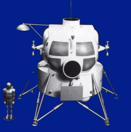
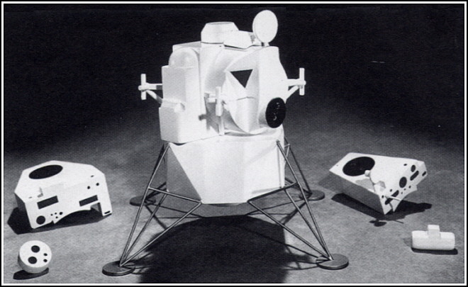
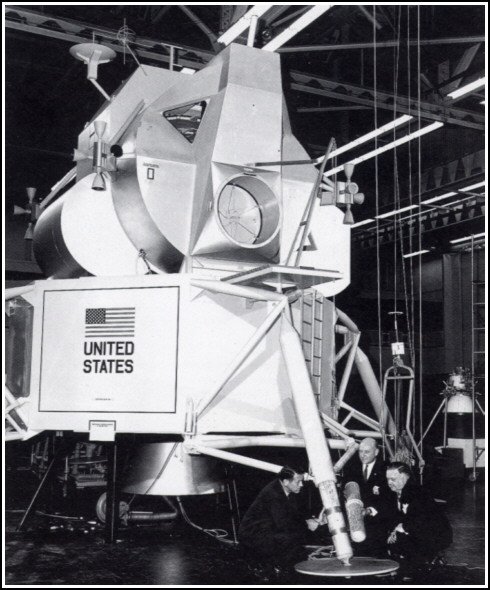
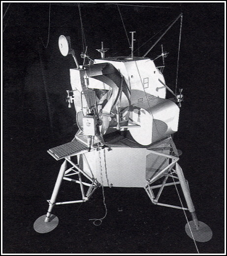
THE TM-1 MocK-up, MARCH 1964. The LM's design was now greatly refined, It was still a twostage vehicle, with the descent stage serving as the launch pad for the ascent stage. In 1964, Grumman unveiled its wooden TM-1 mock-up to NASA. In order to save weight, the LM now had four folding legs instead of five fixed ones. The LM still lacked a ladder, as it was felt that if it bent upon landing, there would be no way for the crew to descend; thus, a knotted rope was supplied instead, Astronauts, however, found it impossible to climb up the knotted rope.


THE TM-1 MOCK-UP REVIEW, APRIL 1964. Due to accessibility concerns, the LM now has a ladder down the side, but it still has the round front docking hatch. As the landing legs had to be able to absorb great impact upon landing, they were fitted with internal crushable aluminum honeycomb cartridges. This was much lighter and simpler than a hydraulic system, and it only had to work once. One of these cartridges is shown being held.

 
THE M-5 MOCK-UP, OCTOBER 1964. In this mock-up, the first all-metal one, the LM nears its final form. The vehicle now has a ladder down the front leg, and the size of the footpads has been enlarged, as there was great concern about the hardness of the lunar surface. As the LM was going to fly only in the vacuum of space, it did not need to have any aerodynamic qualities whatsoever. Thus antennas, legs, rockets, and supplies could be attached externally wherever they were needed.


ASTRONAUTS TRAINING ON THE M-5 MOCK-UP, OCTOBER 1964. Astronauts participated in every step of the LM's design, and they were instrumental in encouraging many changes, M-5 was the product of two years of configuration studies. Every part of the LM's system was scrutinized. One of the astronauts' major concerns was that they had great difficulty getting their square backpacks in and out of the round hatch.


WERNHER VON BRAUN EXAMINING THE M-5 MOCK-UP, NOVEMBER 1964. NASA was extremely pleased with the M-5 and in the end suggested only 120 minor changes. The design had to be frozen shortly so that actual construction could begin in 1965. The crew cabins' two small triangular windows are plainly visible. Eliminating the large glass windows saved weight and simplified construction. The crew members just had to keep their faces close to the small windows to have the same field of vision the larger windows offered.


THE FINAL DESIGN OF THE LUNAR MODULE, 1965. The LM design was now frozen, and construction of test and flight spacecraft could begin. The basic structure of the descent stage was cruciform, with four propellant tanks; the ascent stage was cylindrical, with a flat face and two propellant tanks. The vehicle had 18 rocket engines, the ascent stage, the descent stage, and 16 reaction-control thrusters for maneuvering.


THE BASIC ASCENT STAGE STRUCTURE. Grumman decided on a hybrid approach to the construction of the basic ascent stage, using aluminum alloy skins with titanium fittings and fasteners. Areas of critical structural loads were welded, but rivets were used where welding was impractical. The basic ascent stage structure was made up of three sections: the front face, the midsection, and the aft equipment bay.


THE STRUCTURE OF THE LUNAR MODULE DESCENT STAGE. The cruciform descent stage was the unmanned portion of the LM and represented two-thirds of the vehicle's weight. It had to be heavier because it supported the ascent stage; it had to absorb the impact of landing and act as the launch platform. The descent stage was covered with a heavier H-film thermal blanket than the that of the ascent stage was because it was exposed to engine exhaust from the RCS thrusters.

 
Go to LM Specifications